Parallel Circuits
Imagine an electric current leaving a battery. If the resistors are connected in such a way that part of the current can go through one resistor and the rest of the current can go through another resistor, then the circuit is a parallel circuit.
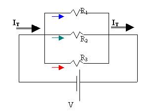
IT is the total current of the parallel circuit. You would measure this current anywhere before or after the three-way split leading to the three resistors. In between the junction and R1, you would measure I1. Between the junction and R2, you would measure I2 etc.
Since the total current, IT, splits up into three different groups of electrons, each traveling their route,
IT
= I1 + I2
+ I3 +….
In parallel circuits, all resistors, regardless of their resistances, experience the same voltage drop or potential difference because they all have the same entry and exit points (junctions).
VT = V1 = V2 = V3
=Vn
If we divide the current formula by the voltage relationship we obtain:
or RT =
[R1-1 + R2-1 + R3-1
+ …]-1
Example 1
12W 12W 12W
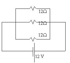
a. What is the total resistance of the circuit?
RT =
[R1-1 + R2-1 + R3-1]-1
RT =
[12-1 + 12-1 +12-1]-1 = 4 W
b. What is the total current?
IT = V/RT = 12/4 = 3 A
c. What voltage (V1) would be measured across each individual resistor?
12
V (Voltage is constant in parallel.)
c.
What current is drawn out by
each resistor?
I1 = V/R1 = 12/12 = 1A. The rest also
draw 1 A each, for a total of 3A.
Example 2
The drawing seems confusing, but note that it is a parallel circuit because the electrons have a “choice”. At the junction (shown by the red dot) the electrons either follow the green route or the orange route.
Use I1 = 1A; I2 = 0.5 A; R1 = 10W.
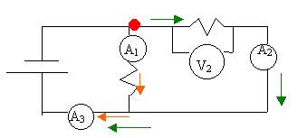
- Find V2.
Remember voltage is constant in parallel. So if we find V1,
we will know V2.
V1 = I1R1 = 1(10) = 10 V.
V2 = V1 = 10 V.
- Find R2.
R2= V/I2 = 10/0.5 = 20W.
- Use two methods to arrive at RT.
(1)
RT = [R1-1
+ R2-1 ]-1 = [20-1 + 10-1
]-1= 6.7 W.
(2) IT
= I3 = I1 + I2 = 1 + 0.5 = 1.5 A.
RT = V/ IT =10/1.5 = 6.7 W.
Example 3
In a parallel circuit, what effect does adding more resistors have on total current?
Current increases!
In a series circuit, adding more resistors increases
total resistance and thus lowers current. But the opposite is true in a
parallel circuit because adding more resistors in parallel creates more choices
and lowers total resistance. If the same battery is connected to the
resistors, current will increase. Not convinced? Try it:
[10-1 + 10-1]-1 = 5 W, but add
a resistor in parallel and you get [10-1 + 10-1 + 10-1]-1 = only 3.3 W. With
less resistance, you’re faced with a higher total current.
Another interesting thing about parallel circuits is that if
one component is turned off, the other pathways are still viable, so that
electrons can continue to flow through the circuit. This is the reason that
most lights and sockets in a home are wired in parallel.