2. (JUNE 2000 416): Which of the following is NOT a unit of electric energy?
A. kWh
B. J
C. V
D. Ws
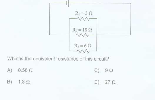
3. (JUNE 2000 416): The following electric circuit consists of a battery and three resistors (R1, R2 an R3).
Sample Questions:
2. (JUNE 2000 416): Which of the following is NOT a unit of electric energy?
A. kWh
B. J
C. V
D. Ws
3. (JUNE 2000 416): The following electric circuit consists of a battery and three resistors (R1, R2 an R3).
4. (JUNE 2000 416): The following electric circuit consists of a power supply, two resistors and three ammeters. R1 has a resistance of 10 W and R2 = 5 W. Ammeter reads 9A.
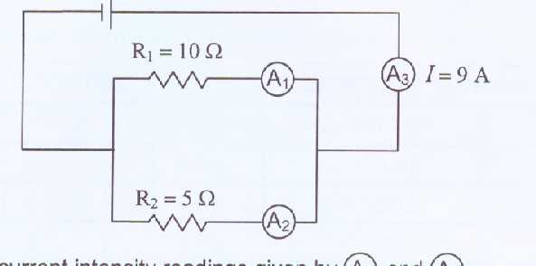
What will be the current intensity readings given by A1 and A2?
A. A1 = 9 A; A2 = 9 A
B. A1 = 6 A; A2 = 3 A
C. A1 = 4.5 A; A2 = 4.5 A
D. A1 = 3 A; A2 = 6 A
Not convinced? See a longer solution.
5. (JUNE 1999 416): The following electric circuit consists of a power supply, two resistors and a voltmeter, which reads 40 V.
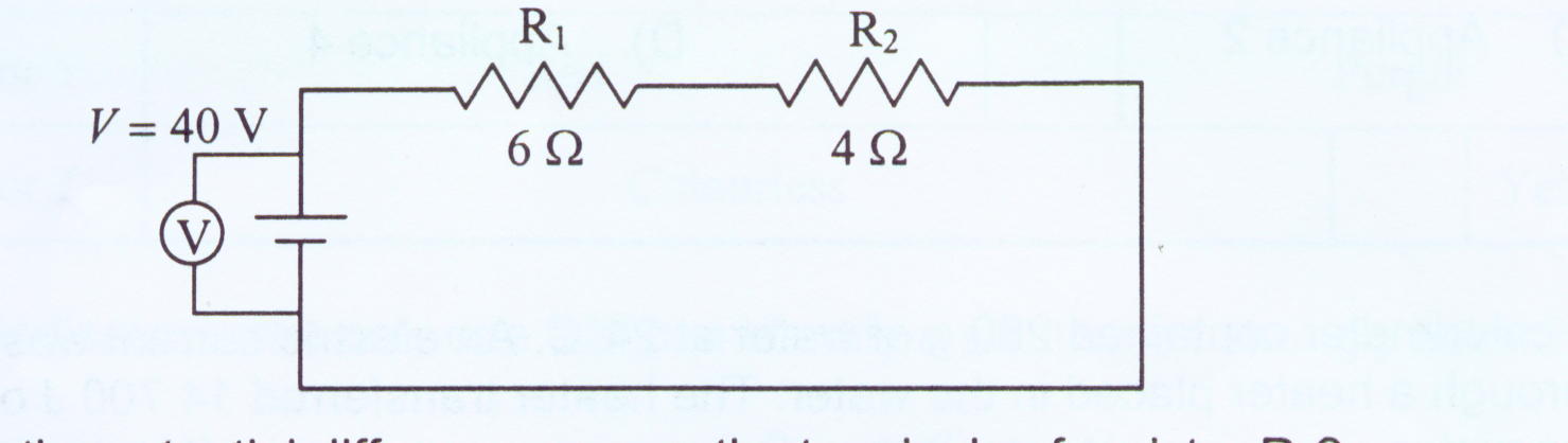
What is the potential difference across the terminals of resistor R2?
A. 10 V
B. 16 V
C. 20 V
D. 40 V
6. In an electric circuit the potential difference across the terminals of a resistor was set at different levels and the resulting current intensity was measured. The measurements are recorded in the table below.
|
Potential Difference,V, (V) |
Current Intensity, I, (A) |
|
0 |
0 |
|
5 |
1 |
|
20 |
4.1 |
|
35 |
7.1 |
|
40 |
8.1 |
Draw a graph using the above data and then use the graph to determine the resistance of the resistor.
No graph = no marks!
Answer
: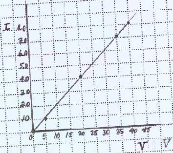
G=I/V= slope = (8.1-0)/(40-0) = 0.20 S but we want R=1/G=1/0.20 = 5.0 W.
Notes:
|
|
Also Known as |
Measured in.. |
Units are equivalent to |
Related to .... |
|
Voltage |
Potential difference |
V= volt |
J/C = Joule per coulomb(charge held by large group of electrons) |
Water pressure, based on how much water is in reservoir connected to your home. |
|
Current Intensity |
amperage |
A = amp or ampere |
C/s= coulomb per second |
How much water is actually flowing out of your hose per second. |
|
Resistance |
|
W .= ohm |
Js/C2 |
Think of a resistor as an obstacle inside your hose. |
|
Conductance |
|
S = siemen |
C2/(Js) |
Similar to current but also tied in to voltage |
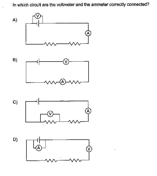
Measuring Voltage and Current.
If you look at question1, choice A, you'll see the correct way of hooking up a voltmeter, always in parallel to whatever you're measuring. Voltage is, after all, potential difference, so it has to measure the difference between the energy per coulomb before and after the electrons flow through the battery or resistor.
The ammeter, however cannot offer electrons any choice. It has to be connected in series, not parallel.
What is a Parallel Connection?
Resistors are said to be in parallel if electrons have a choice to flow through one resistor but not the other. Question #4 is an example of a parallel circuit.
What is a Series Connection?
Resistors are said to be in series if electrons have no choice but to flow through each resistor to and from the battery. Question #5 is an example of a series circuit.
Ohm's Law
V= IR applies to both series and parallel circuits. But in applying it, you have to keep the following important things in mind:
|
Type of circuit |
Voltage |
Total or equivalent resistance |
Current |
|
parallel |
Is the same for all resistors connected in parallel. This happens because in parallel electrons have, on their way to different resistors, the same entry and departure point, and so have the same potential difference. |
1/Re = 1/R1+1/R2... example; in #3: 1/Re=1/3+1/18+1/6=10/18; Re = 18/10=1.8W Re in parallel is always smaller than any individual resistance. |
It = I1 + I2 + I3; This makes sense because although the current splits up in parallel, the electrons all meet again at some point in the circuit. |
|
series |
Vt = V1 + V2 + V3 ...; So a smaller resistor will experience a smaller voltage drop. |
Rt = R1 + R2 + R3... |
Current is |